Chain Spline in UE4
09 Jan 2017 #Blueprints #UE4A breakdown of my approach to procedurally generating chain links along a spline in UE4 with adjustable ends in order to appear that the chain is attached to a given point.
Blueprint Breakdown
The Problem
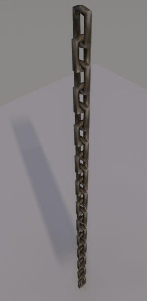
For the Hollowed project, there was a need to create chains. Initially, a single chain link was made. The chain itself was made manually by level designers. The problem with this direct approach meant that the chain only functioned in a straight line.
Other complications appeared with combining static meshes in UE4, such as the combined mesh inheriting each material from the static meshes it is made from. This could potentially be expensive because more repetitive draw calls are being made for each material applied to the combined mesh when they are all using the same material.
Since this combined mesh was used in levels already, I had to export the combined mesh, change the material assignments to a single material, and re-import it back into UE4.
A spline could be used for other situations where slack is needed in the chains.
My Solution
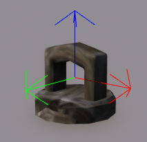
Anticipating that the chain would need to appear attached to surfaces, I created a mesh to be used as the ends for the chain. A simple mesh was made from half of the chain link and half of a low poly cylinder mesh. With this mesh created, I began working on the blueprint and attached this mesh at the first and last point on a spline. I put all the functionality in the construction script so level designers could see the blueprint in action before gameplay. I created exposed parameters so the user could rotate the ends to make their placement believable to the level. For the end meshes to appear correctly on the spline, I had to move the pivots of the meshes. I also included a translation offset attached to the last spline point of the end meshes because sometimes the generation of chain links did not align perfectly with the last spline point.
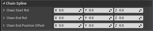
The image to the right shows the exposed parameters for the chain link at the beginning and end of the chain. The level designer would use these values to to roate and position the ends of the chain link to match the surface the chain is mounted to.
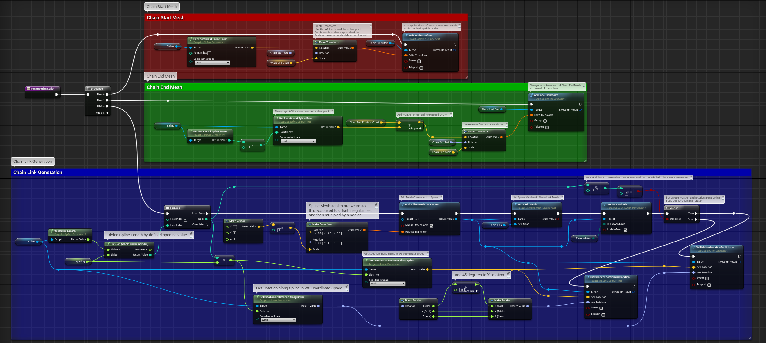
The Red section shows the breakdown for the chain link mount at the beginning of the chain. The Green section is for the chain mount at the end of the chain is similar but uses an optional translational offset to visually fix any link overlap
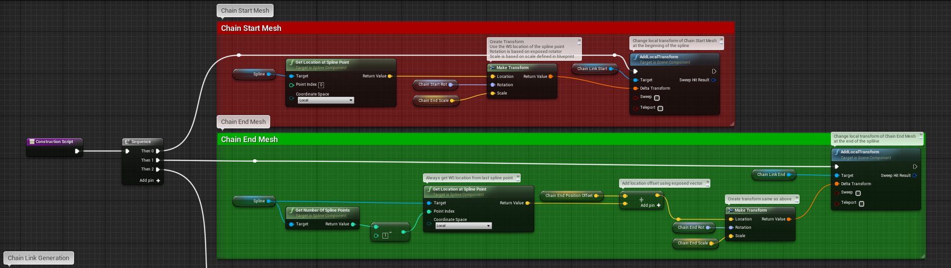
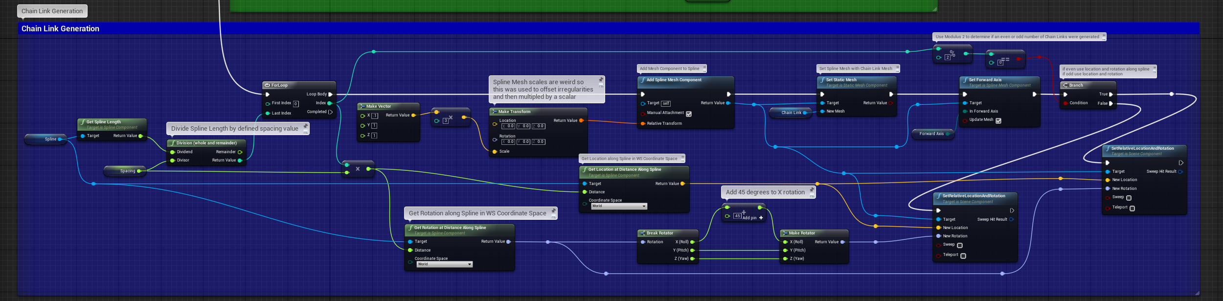
The Blue section below shows the logic needed to place chain links along the spline and alternate the rotation of the links so that they appear as links in a chain.